


Discover the Key Facts
Type of structure
Individual (I)
Module Direction
East-West (EW)
Module Layout
Level (H)
Number of supports
Three-legged
Number of modules
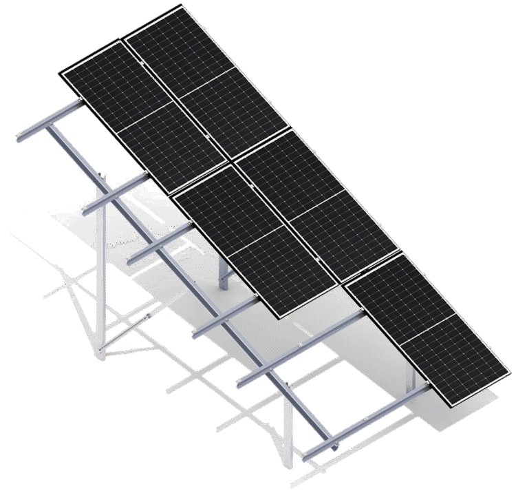
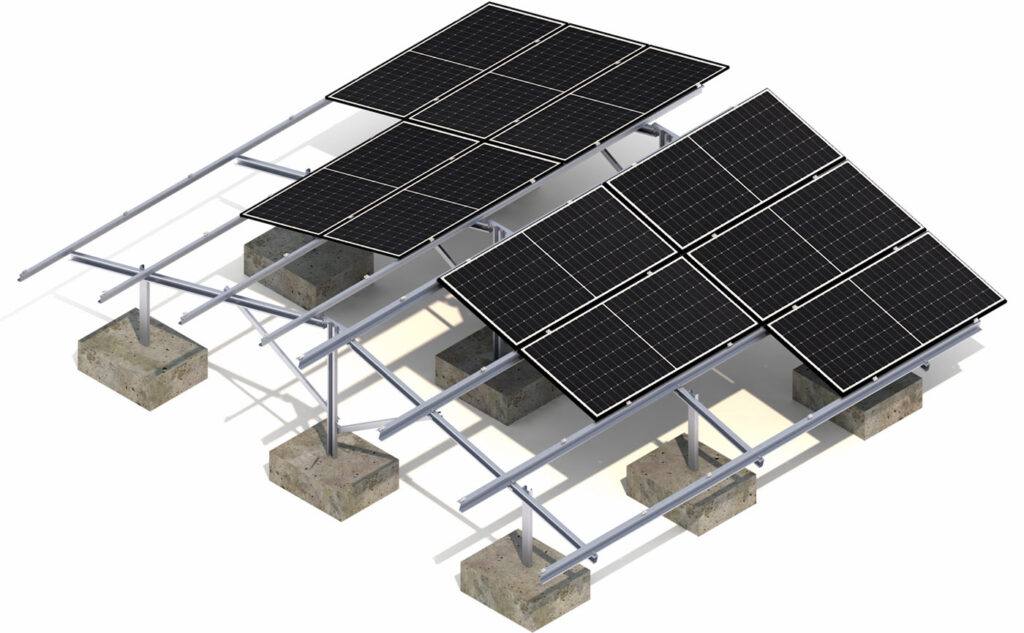
3×3 + 3×3 (+6)
Design Description
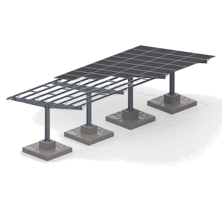
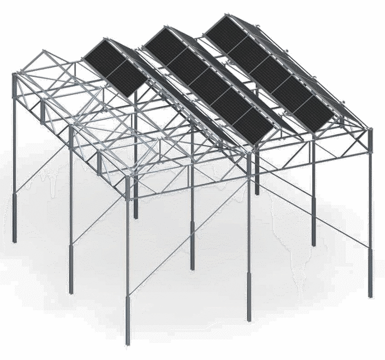
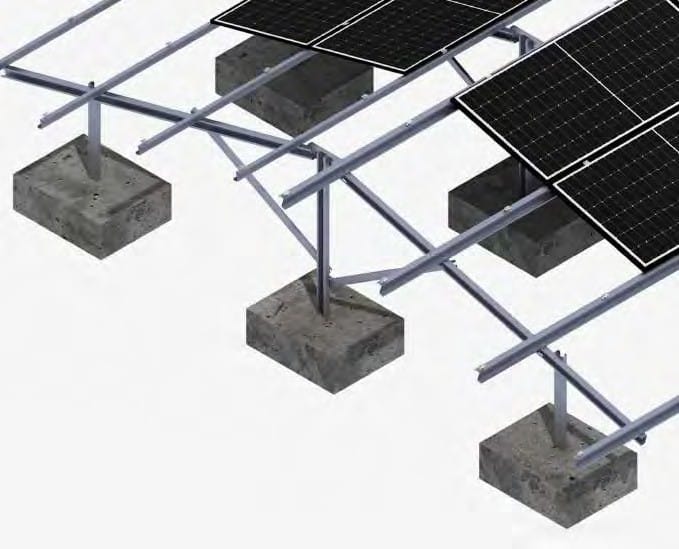
A multi-piece ground structure made of Magnelis™ sheet metal, designed for use on soils and sites where additional ballast is required.
Before production, the PZT must be provided along with the module assembly instructions.
Ideal for constructing structures above 50 kW that require a building permit and whose components need to be optimized based on the structure's foundation location.
This system is designed for ground-mounted installations where the choice of structure is based on the need to use additional ballast.
An assembly system consisting of individually selected structural components, including purlins, transoms, and legs, which allows the structure to be used only for predetermined modules and their sizes.
The option to use a hybrid system in which the leg(s) can be weighted with ballast in areas where it is not possible to drive them to a specific depth.
The bolting system used to assemble the purlins, transoms, and legs requires no maintenance as long as installation is performed in accordance with the instructions.
A multi-piece ground structure made of Magnelis™ sheet metal, designed for use on soils and sites where additional ballast is required.
Before production, the PZT must be provided along with the module assembly instructions.
Ideal for constructing structures above 50 kW that require a building permit and whose components need to be optimized based on the structure's foundation location.
This system is designed for ground-mounted installations where the choice of structure is based on the need to use additional ballast.
An assembly system consisting of individually selected structural components, including purlins, transoms, and legs, which allows the structure to be used only for predetermined modules and their sizes.
The option to use a hybrid system in which the leg(s) can be weighted with ballast in areas where it is not possible to drive them to a specific depth.
The bolting system used to assemble the purlins, transoms, and legs requires no maintenance as long as installation is performed in accordance with the instructions.
We recommend that our Technical Department first review the design of any structure to be manufactured to ensure it is suitable for installation in a specific wind and snow zone.
This design is intended for specific, predefined wind and snow zones and features individually selected ballast. To initiate production, an advance payment is required, the amount of which is specified in the offer.
1
2
3
4
5
Download as a PDF
Download the Product Sheet
WATCH THE ANIMATION
1
Bolt
2
Purlin
3
Long Leg
4
Zastrzał
5
Short leg
Product Specifications
G-B-I-EW/H/3/3×3-3×3
Type of substrate
Soil (S)
How to Assemble the Structure
Ballast structure (B)
Type of structure
Individual (I)
Module Orientation
East-West (EW)
Module Layout
Level (H)
Number of supports
3
Number of PV modules
3×3 + 3×3 (+6)
Module Type
Standard/Bifacial
The shape of the pole
Single-piece leg – C profile / Two-piece leg – CW profile
Does the design require additional ballast?
Yes
Is it possible to use a hybrid solution (piling + ballast)?
Yes—the option to add additional ballast
Minimum number of modules on the structure
18
Height of standard clamps (mm)
35
Thickness of standard clamps (mm)
5
Maximum PV module size (mm)
–
Distribution Method
Made to order
Structural Base Components
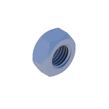
M10 TZN Hex Nut
NM10Z

M10 300HV Washer, ISO 7093-1 TZN
PSZM10Z
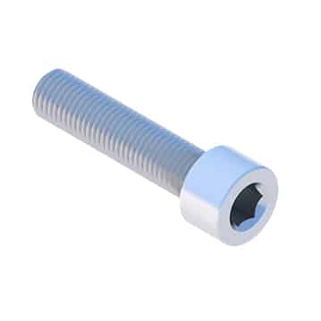
M8x100 Allen screw, DIN 912 A2
SIM8X100A2
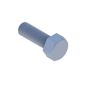
M10X20 TZN Hex Head Screw
SM10X20Z
Other Mounting Components
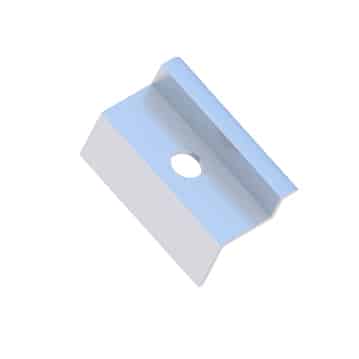
End Clamp 30/32/35/40 Nature/Black
KLK50/30(32/35/40)ALN
KLK50/30(32/35/40)ALCZ
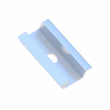
50 Universal Center Clip, Nature/Black
KLSR50ALN
KLSR50ALCZ
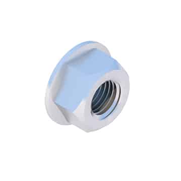
M8 Serrated Flange Nut, DIN 6923 A2
NKM8A2
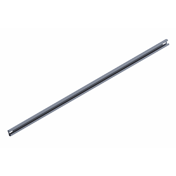
Zastrzał
Back to the list
Contact our expert

Do you have another question?