

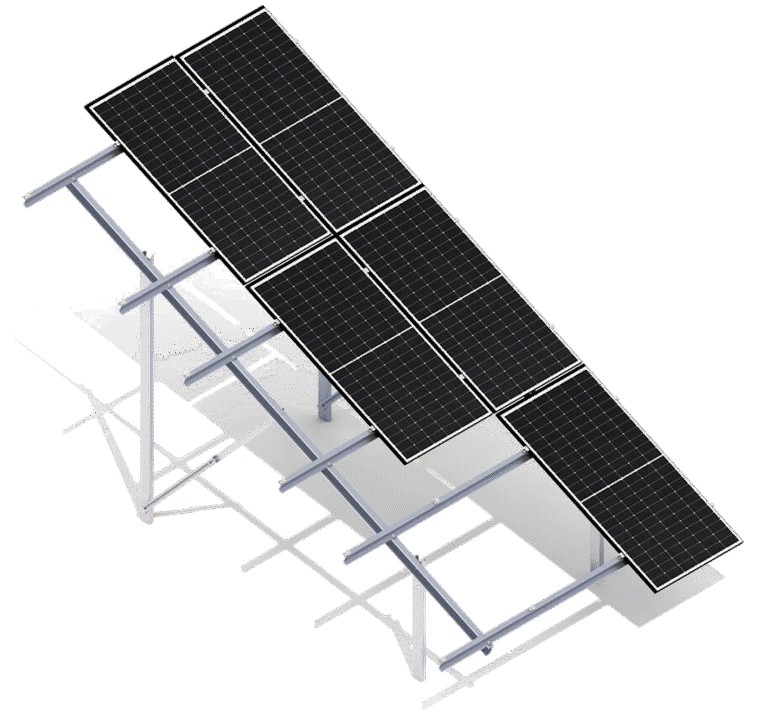
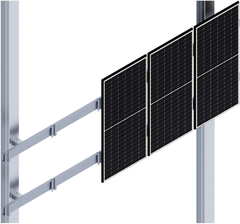
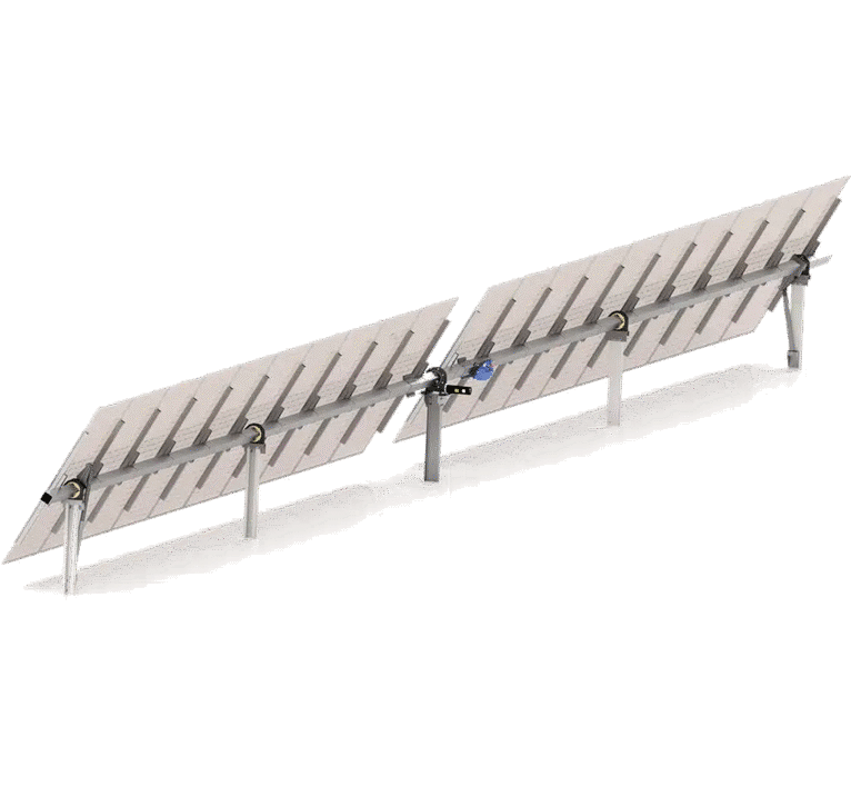
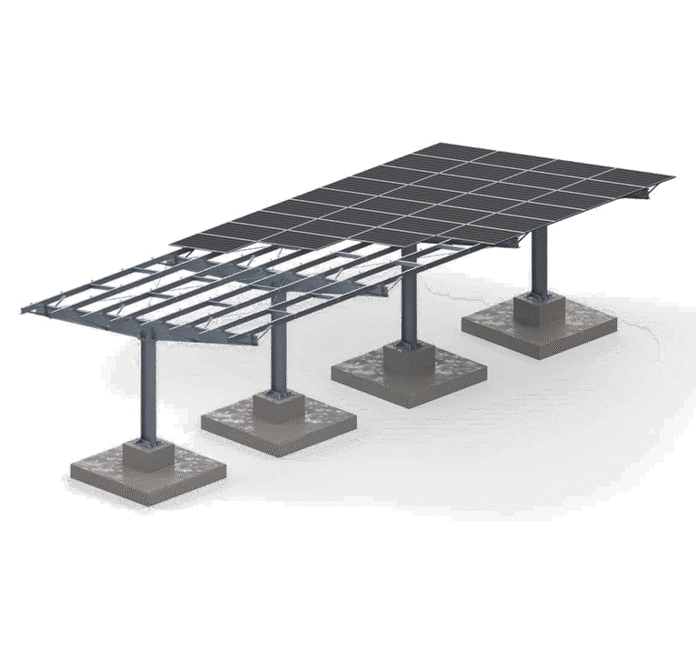


Discover the Key Facts
Type of construction
Piled (P)
Type of structure
Single-axle (1AT)
Module Direction
East-West (EW)
Module Layout
Vertical (V)
Number of logs
1
Design Description
Strength verification of the structural parameters conducted by a specialized laboratory.
The use of an advanced astronomical algorithm to control the orientation of the panels relative to the sun's current position.
Tracker lengths vary depending on the number of strings, and the selection of the number and length of trackers is determined on a case-by-case basis for each project.
An intuitive system for installation and startup configuration.
Design principles implemented according to the DFA (Designed for Easy Assembly) methodology.
Customizable alarm and notification management.
Split, adaptive plain bearings that adjust their position to accommodate variable thermal or geometric deformations of the support beam.
A backtracking algorithm that prevents and minimizes row shading.
The use of an intermediate purlin to increase the central support area of a load-bearing purlin connected to a PV panel,
Zigbee® wireless communication system or RS-485 wired communication system.
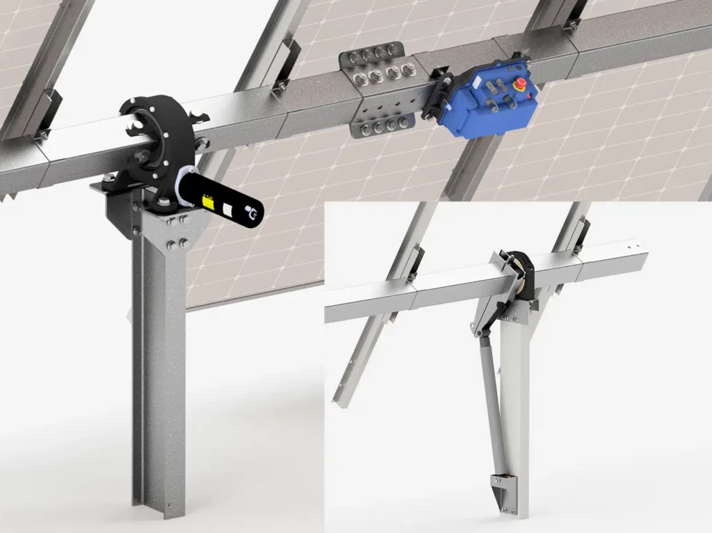
Drive leg aligned with the support columns (the length of the support columns is selected on a case-by-case basis depending on the project’s geographical and geological conditions).
Remote monitoring and preventive maintenance to reduce system downtime (easy integration with a SCADA system using the Modbus TCP/IP standard).
Standardization of structural components.
The ability to customize the tracker's operation based on the order of the rows and the slope of the terrain.
Optimization of bolted joints.
Wind Speed Safety System (Safe Positioning of PV Panels).
The ability to use various maintenance modes related to the position of the panels, such as snow removal and cleaning.
Option to use a snow level sensor.
The ability to monitor current and historical system parameters in the cloud.
Strength verification of the structural parameters conducted by a specialized laboratory.
The use of an advanced astronomical algorithm to control the orientation of the panels relative to the sun's current position.
Tracker lengths vary depending on the number of strings, and the selection of the number and length of trackers is determined on a case-by-case basis for each project.
An intuitive system for installation and startup configuration.
Design principles implemented according to the DFA (Designed for Easy Assembly) methodology.
Customizable alarm and notification management.
Split, adaptive plain bearings that adjust their position to accommodate variable thermal or geometric deformations of the support beam.
A backtracking algorithm that prevents and minimizes row shading.
The use of an intermediate purlin to increase the central support area of a load-bearing purlin connected to a PV panel,
Zigbee® wireless communication system or RS-485 wired communication system.
Drive leg aligned with the support columns (the length of the support columns is selected on a case-by-case basis depending on the project’s geographical and geological conditions).
Remote monitoring and preventive maintenance to reduce system downtime (easy integration with a SCADA system using the Modbus TCP/IP standard).
Standardization of structural components.
The ability to customize the tracker's operation based on the order of the rows and the slope of the terrain.
Optimization of bolted joints.
Wind Speed Safety System (Safe Positioning of PV Panels).
The ability to use various maintenance modes related to the position of the panels, such as snow removal and cleaning.
Option to use a snow level sensor.
The ability to monitor current and historical system parameters in the cloud.
1
2
3
4
5
6
7
8
9
10
11
12
13
14
Download as a PDF
Download the Product Sheet
WATCH THE ANIMATION
1
Central Drive
RBTSOLAR-1AT-TGB-CD
2
Tracker beam - short
RBTSOLAR-1AT-SB
3
IPE 160 Motor Mount
RBTSOLAR-1AT-CD-C
4
Beam Connector
RBTSOLAR-1AT-B-C
5
TCU Control Unit
RBTSOLAR-1AT-P4Q-CTR
6
Tracker beam - long
RBTSOLAR-1AT-MB
7
Upper shock absorber arm
RBTSOLAR-1AT-D-UA
8
Main Beam Bearing
RBTSOLAR-1AT-TGB-MB-B
9
Lower shock absorber mount
RBTSOLAR-1AT-D-LJ
10
Main leg
RBTSOLAR-1AT-MC
11
Purlin
RBTSOLAR-1AT-JST
12
Purlin Guide
RBTSOLAR-1AT-JST-R
13
Clamp
RBTSOLAR-1AT-JST-J
14
Shock Absorber
RBTSOLAR-1AT-TGB-D
Product Specifications
T-P-1AT-EW/V/1P
Type of substrate
Land (GR)
How to Assemble the Structure
Pile Foundation (P)
Type of structure
Single-axis (1A) Tracker (T)
Module Orientation
East-West (EW)
Module Layout
Vertical (V)
Maximum PV module length
2300
Tracking Type
Automatic, horizontal1
Tracking Algorithm
Accurate astronomical models; Tracking precision = 2.0°2
Trading Range
±60°
Land Coverage Ratio
Any configuration specified by the customer (from 32% to 50%)
Compatibility with PV modules
Standard/Bifacial
Powertrain
1 independent horizontal rotation drive per tracker
Number of modules per tracker
max 60 (customizable)
Power Options
dedicated photovoltaic modules + 230V AC 50/60 Hz battery3
Communication
Zigbee® wireless communication system or RS-485 wired communication system
Monitoring
Modbus TCP/IP, integration with a SCADA-type system is possible
Adaptation to the slope of the terrain
up to 6% in the N-S direction
Wind resistance
1) Up to 80 km/h in any position
2) Up to 140 km/h in a horizontal position or any other position defined as neutral
Distribution Method
Custom Order
1. It is recommended to align the tracker's axis along the north-south direction.
2. Traction can be individually adjusted to the terrain.
3. The option to use a UPS.
Back to the list
Contact our expert

Do you have another question?